

At first, the strength of materials was based on what failed. A wooden lever broke (at the side opposite the fulcrum). A uniformly loaded roof beam broke on the underside between two supports because the underside of the beam was in tension.
In both cases the failure was caused by tension exceeding the strength of the wood. The simple solution was to make beams wider but builders found that using beams on edge made them far stiffer and less likely to break compared to making them wider.
They also discovered that wooden poles used as columns to support a heavy roof could fail in compression (if they did not bend or buckle).Some types of wood were far stronger than others but all wood was much weaker in tension applied at 90 degrees to the fibre (grain) direction. This is why Roman soldiers' shields were made with crossed grain plywood.
Wood and animal sinews were both springy. They would return to their original shape if stretched which proved useful for stored energy weapons like bows, crossbows and catapults.
Average Ultimate tensile strength parallel to grain (axial load)
(psi = pound per square inch).
Loblolly pine 88 Mpa (12,760 psi )
Sitka spruce 75 Mpa (10,875 psi)
Red Oak 101 Mpa (14,645 psi)
Bamboo(Gigantochioa Apus) 290 Mpa (42,050 psi)
ASTM A36 steel, structural 400–550 Mpa (58000 - 79750 psi)
Rock was typically strong in compression but weak in tension. A long stone beam (lintel) over a doorway or window would bend and break if the stones on top the lintel were too heavy. Stone was typically strong in compression but weak in tension so builders developed the semicircular arch where all the stones were in compression.
But when people tried to build large stone structures like the pyramids they found that the weight of stone would crush stones at the bottom of the pile. There was an ultimate limit to compressive strength of rock.
Some rock was brittle and volcanic glass (obsidian) very brittle although it provided extremely sharp cutting edges. Other rock was extremely hard and could be used to grind or cut other material. (Diamonds are still the hardest material found naturally on Earth).Clay could be formed into bricks and baked in ovens to make an artificial stone useful for building. The Roman invention of a durable cement permitted them to make brick walls and aqueducts that out-lasted many other buildings for thousands of years. When metals were discovered they had some useful properties. They could be cast, hammered, filed or ground into shape and some, like bronze and steel, provided tough, cutting tools and weapons and leaf and coil springs.
Until the scientific and industrial revolution, most bridge builders, architects, mechanics and engineers relied on preceding designs and traditional knowledge and practices. Then, in 1687, Isaac Newton published his work on the three universal laws of motion providing the basis for modern applied or engineering mechanics.
About 1750, Leonhard Euler and Jacob Bernoulli devised a simple beam theory as way of calculating the load-carrying and deflection characteristics of beams. However, it was not widely used until the design of the Eiffel Tower and the Ferris wheel in the late 19th century after which it became an essential part of mechanical engineering and the Second Industrial Revolution.
The definitive modern work was largely developed by Stephen Timoshenko, a Ukrainian and, later, an American engineer, between 1922 and 1962. Timoshenko wrote a dozen seminal works about engineering mechanics, elasticity and strength of materials and other aspects of engineering mechanics, which have been translated into half a dozen foreign languages so that now all mechanical and civil engineers use his work.
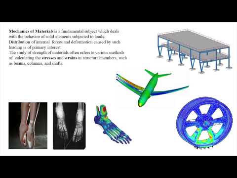
The strength of a material is its ability to withstand an applied load without failure or permanent deformation. A load applied to a structural part, such as a beam, column or drive shaft, induces internal forces called stresses. The stresses cause deflection or deformation called strain.
Materials have properties such as yield, ultimate, compressive and shear strengths, Young's modulus and Poisson's ratio. Strength also depends on the shape, length, width, thickness and changes in geometry such as holes as well as the bending, compressive, shear, fatigue and static and dynamic loading.
Young's modulus E, or the modulus of elasticity in tension, is stress divided by the axial strain (mechanical extension).Thomas Young described the characterization of elasticity that came to be known as Young's modulus, in 1807, however, the concept of Young's modulus was first used by Leonhard Euler in 1727 and Giordano Riccati in 1782. Young's modulus for steel is about 3 times larger than for aluminum which means, for similar structures and loads, aluminum will stretch (or deflect) 3 times more than steel.
Siméon Poisson's ratio is the amount of transverse elongation divided by the amount of axial compression of a material under load. (The width of the material increases as the length is compressed shorter). Many solid materials have Poisson's ratios in the range of 0.2-0.3. Soft materials like rubber may have Poisson's ratio is near 0.5.
The stresses and strains that develop within a mechanical part must be calculated to discover whether stress remains within a safe working range, (that is the elastic range, including a safety factor) so that the part will not break or be permanently deformed. Steel H-beams (or I -beams) are the most used sections for beams because this shape provides the lowest stress and deflection for any load and for lowest cost. The reason is that it has the best 'second moment of inertia (I)' with reasonable stability for off centre loads. (Although is very poor in torsion).
For example, after the weight of a roof is calculated, a simple beam may be selected from a range of standard steel H-beams.
A S18 x 54.7 H-beam is 12 inches deep with a flange width of 6.001 inches. It has second moment of area (I) of 804 in4 about the horizontal axis but only 20.8 in4 about the vertical axis.
For comparison, a solid rectangular bar with a cross section 12 x 6.001 in. has a moment of inertia (I) of, bd3 (width x the cube of the depth) divided by 12
= 6.001 x 12 x 12 x 12 divided by 12 = 864 in4
which is only 7% stronger for considerably more weight.
This beam spanning a distance of 10 feet and loaded at the centre will support a single point load of 76 800 pound if the stress is not to exceed 8000 psi.
The maximum stress = half the section depth x load x span divided by 4 x second moment of area. (for a simple rectangular bar this is b x d3 divided by 12).
Stress = 3 in. x 76800 pound x 120 in. divided by 4 x 864 in4. = 8000 psi. (in4 means inches to the fourth power).
which provides a very conservative factor of safety of about 70 over the ultimate tensile strength of structural steel at 58 000 psi.
The beam deflection under this load would also be calculated to ensure it is acceptable. In which case a larger beam might be selected.
ASTM A36 structural steel has an ultimate tensile strength of 400–550 Mpa (58000 - 79750 psi)

YOU ARE READING
Engineering
Non-FictionDenis Papin built the first steam engine in 1705 and, by 1800, Boulton and Watt had built 451steam engines. In 1870, the British produced 4 million tons of coke for iron and steel production and locomotive and industrial engines. Axel Cronstedt ide...
